42 labelled diagram of motherboard
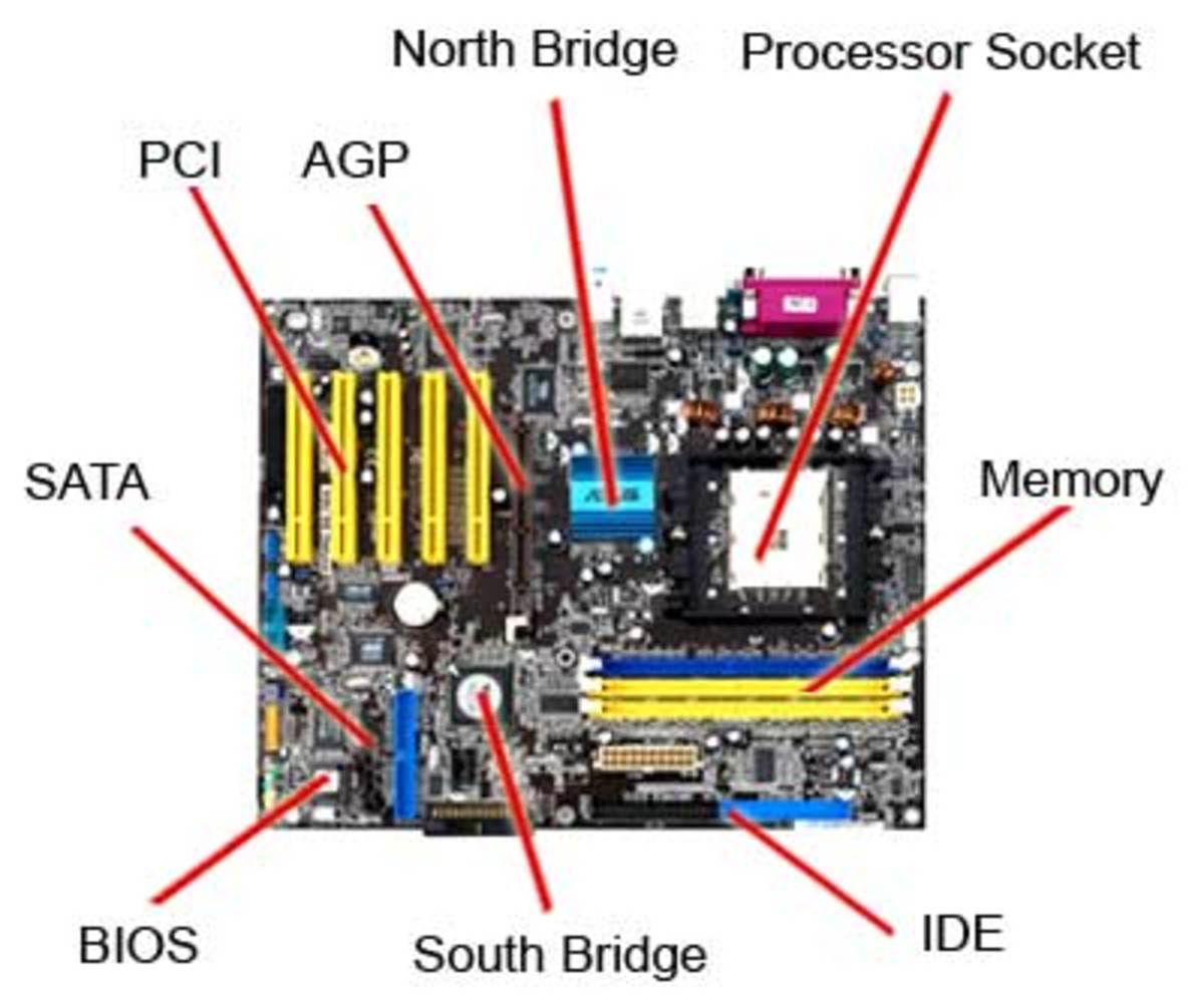
27 Main Parts of Motherboard and its Function - OurTechRoom 9)Power Supply Plug. The primary function of the Motherboard's Power Supply plug is to supply power to the Motherboard and its attached components and peripherals. fig. Power Supply Box provides power to the motherboard and devices like HDD, CDROM, Floppy etc. i) 24 (20 + 4) ATX power supply. Labelling a Motherboard Diagram | Quizlet This motherboard chip provides direct connections for AGP/PCIe, the CPU and RAM South Bridge Part of the CPU chipset. It provides the interface to low speed devices and is often called the I/O Controller Hub (ICH). Compare to north bridge. PCI Slot Allows for expansion cards to be added to the motherboard. Such as Sound cards, video cards etc.
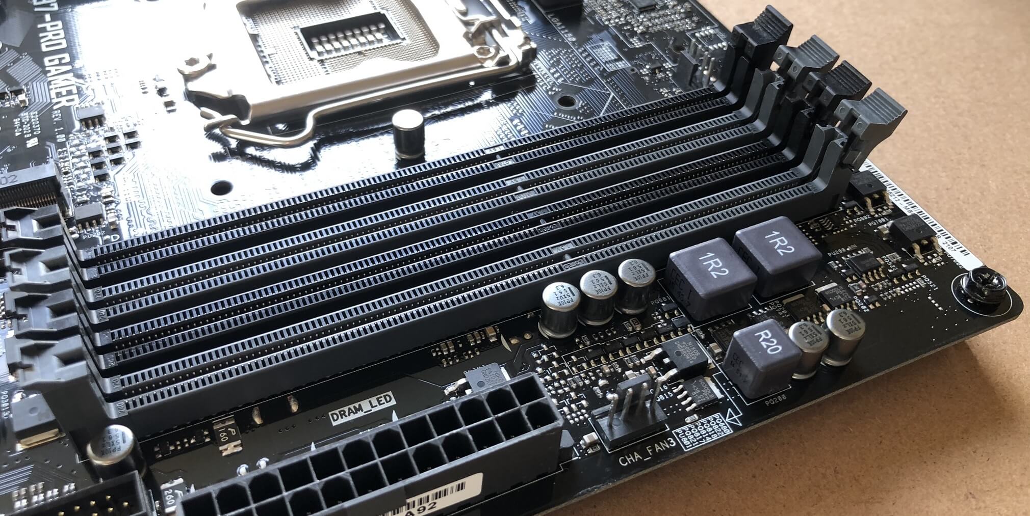
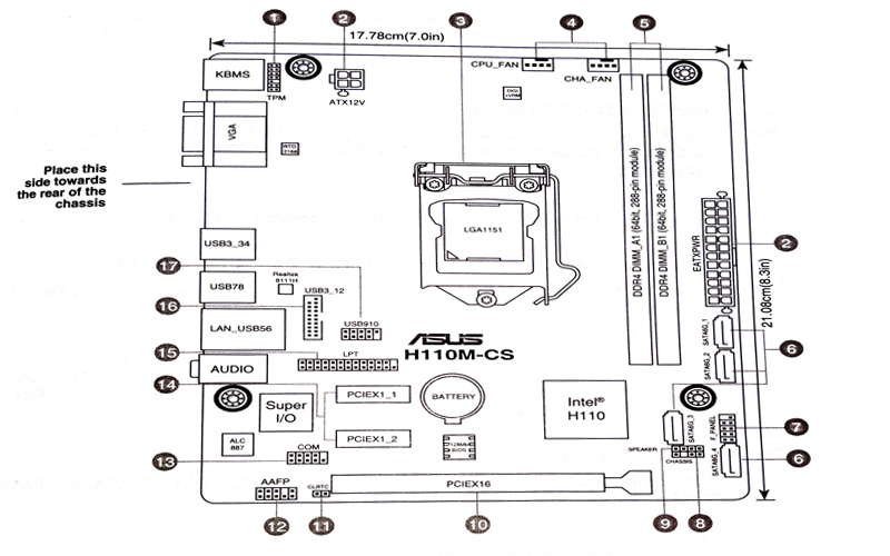
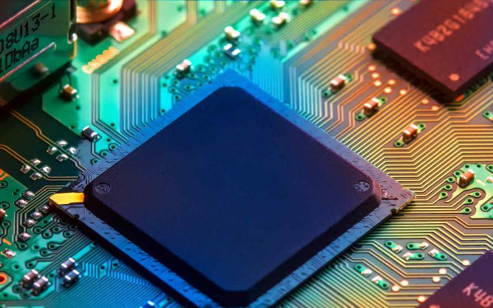
Motherboard Anatomy: Connections and Components of the PC Motherboard Motherboards will typically have a specific connector labeled as the "CPU Fan" header, which is almost always the one closest to the CPU socket. It's important to plug your CPU cooler into this one specifically, since some motherboards will perceive that the CPU cooler isn't plugged in at all if you don't. DIMM Slots
Labelled diagram of motherboard
› writings › consolesSega Saturn Architecture | A Practical Analysis Aug 03, 2019 · Original; Marked; Motherboard Showing 'VA8' revision which includes all components in a single board Remaining RAM chips are fitted on the back Motherboard with important parts labelled eevibes.com › digital-logic-design › draw-the-statehow to draw state diagram of sequential circuit? - EE-Vibes Jun 06, 2022 · The input value that triggers the state shift is the first to be labelled. The value of the output is the number after the slash symbol /. The directed line from state 00 to 01, for example, is labelled 1/0, which means that if the sequential circuit is in a current state with a 1 as an input, the following state is 01 with a 0 as an output. Motherboard Labelled Diagram - Edugeek Motherboard Labelled Diagram. Hi All, Thought this might be of interest for anyone that is teaching GCSE ICT or something. Interactive diagram showing components of a motherboard. Intel® Desktop Board DH61CR Interactive Layout.
Labelled diagram of motherboard. Motherboard Diagram With Labels Pdf : A Computer Motherboard Diagram ... Labeled diagram of acer motherboard. Recently, amd dropped the 64 label and calls this product amd athlon x2. No part of this manual, including the products and software described in it,. By default, the pin labeled "chassis signal" and "ground" are shorted with a jumper cap. By default, the pin labeled "chassis signal" and "ground" are shorted ... How to design a four bit adder-subtractor circuit? - EE-Vibes 05/06/2022 · Designing: A single basic binary adder may do both addition & subtraction tasks. As illustrated in the diagram underneath, a binary circuit may be created by combining an Ex-OR gate alongside every full adder. 4-bit parallel adder and 4-bit parallel subtractor shown below has multiple 4 bit inputs labelled ‘A3 A2 A1 A0’ & ‘B3 B2 B1 B0’. Anatomy of a Motherboard | TechSpot 06/01/2020 · The diagram has a structure labelled LGA1150. This is the name used by Intel to describe the socket used to hold many of their CPUs. The letters, LGA, stand for Parts of Motherboard | Figure out the Anatomy of Motherboard The clock generator of a motherboard synchronizes the functioning of all connected components. It generates a clock signal to generate a metronome to coordinate actions. Switches and Jumpers There are many switches and jumper pins and caps on the motherboard. These DIP switches and jumpers help to configure the motherboard.
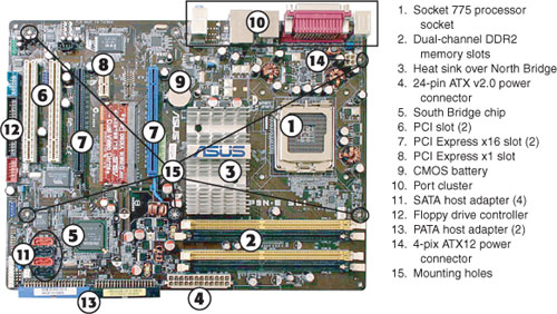
Types of Computer Memory: RAM, ROM and Secondary Memory 25/11/2020 · No matter what’s your input sources, be turning on your computer or typing on your keyboard, it’ll all go to read-only memory (ROM) and performs a power-on self-test (POST) to ensure all components are functioning.. Then, the memory controller will check the memory addresses and perform a quick read/write operation to make sure there are no errors. Power supply unit (computer) - Wikipedia Diagram of a typical XT and AT voltage regulator circuit. Internals of a PSU with passive PFC (left) and active PFC (right) The desktop computer power supply converts the alternating current (AC) from a wall socket of mains electricity to a low-voltage direct current (DC) to operate the motherboard, processor and peripheral devices. Several direct-current voltages are required, … › article › 1965-anatomy-motherboardAnatomy of a Motherboard | TechSpot Jan 06, 2020 · The diagram has a structure labelled LGA1150. This is the name used by Intel to describe the socket used to hold many of their CPUs. ... Motherboard designers use software to help them work out ... Motherboard Parts Diagram | Quizlet Motherboard Parts Diagram | Quizlet Motherboard Parts STUDY Learn Flashcards Write Spell Test PLAY Match Gravity + − Created by dawg29 Terms in this set (15) PCI Card Slot Northbridge Chipset ... Southbridge Chipset ... Processor Socket Case/front-panel connections ... USB header P24 - Aux Power ... Aux 12v Power ... 40-pin eIDE header ...
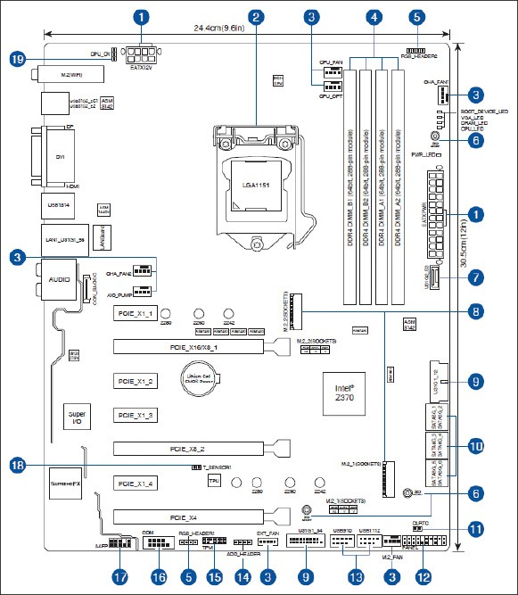
Super Nintendo Architecture | A Practical Analysis 28/06/2019 · Motherboard Showing revision 'SNS-RGB-CPU-01' Earlier revisions had the Sound Subsystem connected as a daughterboard, later ones unified both PPUs Motherboard with important parts labelled. Diagram Main architecture diagram Bus 'A' and 'B' are address buses, the data bus follows the trail of bus 'B' and it's 8 bits wide . A quick introduction. Nintendo … Motherboard Components Labeled - Motherboard Parts and Functions Join us as we take you on a guided tour of the different motherboard components (complete with photos and plain English descriptions): 1. Back Panel Connectors & Ports Connectors and ports for connecting the computer to external devices such as display ports, audio ports, USB ports, Ethernet ports, PS/2 ports etc. Labeling a Motherboard.docx - Labeling the Motherboard This... Labeling the Motherboard This figure shows a diagram of an ATX motherboard. Label as many of the 19 components as you can. Start numbering on a separate page in a Word document. 3 5 24.4cm (9.6in) Q&A. Select and install a storage drive. Lab 5-4: Testing Mode: Select and Install a Storage Drive Select and install a storage drive introduction ... en.wikipedia.org › wiki › Power_supply_unit_(computer)Power supply unit (computer) - Wikipedia 12V only power connector (labelled P1, though it is not compatible with the ATX 20 or 24 pin connector): This is a 10 or 16-pin Molex connector supplying the motherboard with three or six 12 V lines with common returns, a 'supply OK' signal, a 'PSU ON' signal and a 12 or 11 V auxiliary supply. One pin is left unused.
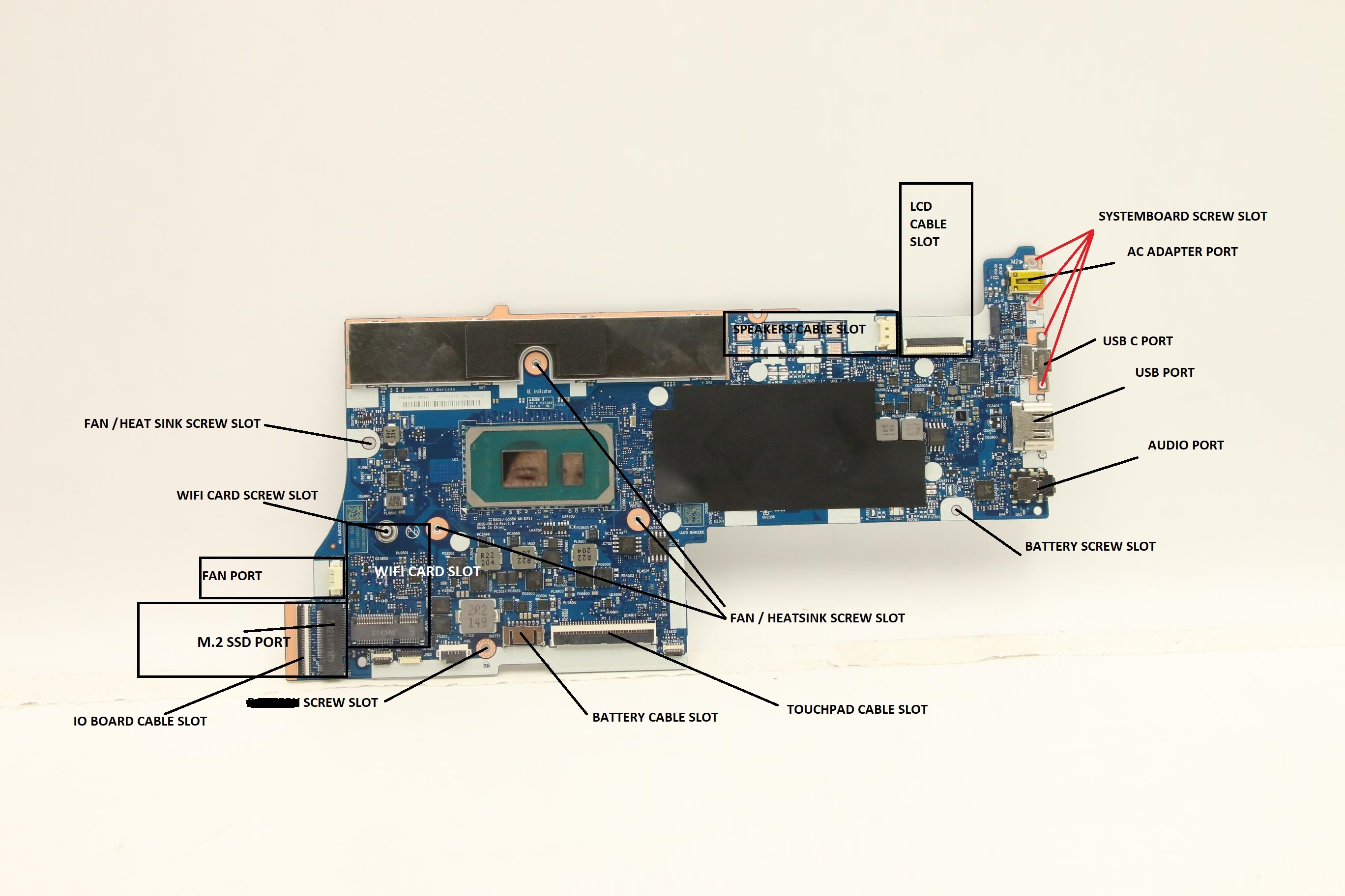
Labelled-System-Board-diagram-for-Lenovo-Ideapad-5-15ITL05 ...
Block Diagram of Computer - Tutorial and Examples | EdrawMax Drawing by hands. Get the paper and pencil and start the work. First, draw the large and broad rectangle in the vertical form. Make three boxes inside the main rectangle figure, and name them as the Control Unit on the above box, the Arithmetic Logical Unit on the box in between, and the main memory on the box below.
Can someone please briefly describe each labelled part in ...
Picture Of Motherboard With Label / Label The Motherboard Labelled Diagram Motherboard diagram with all components labeled. Creating your own labels is easy. Power connector, which is the main power . Guidelines for motherboard diagram with labels. There are several components that comprise a motherboard. Mounting Jumpers Of The Rack Ipc Universal And Optimized from product-help.schneider-electric.com

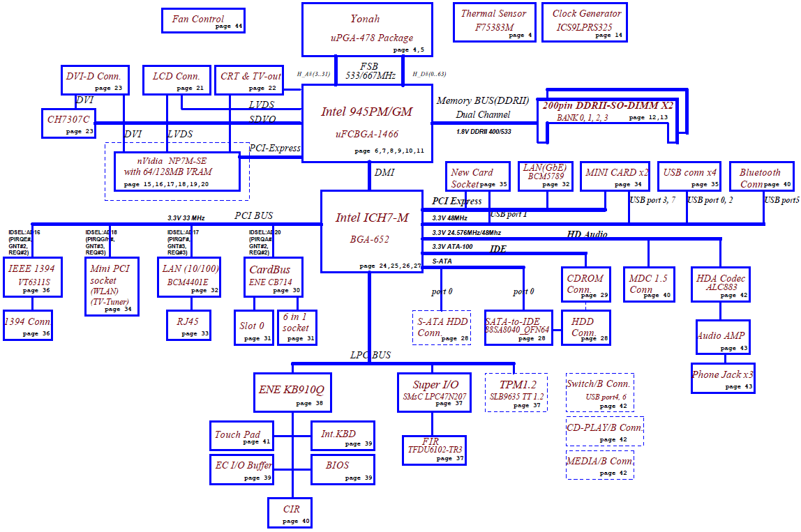
How to work computer motherboard (basic block diagram of computer motherboard,)
How To Find your Motherboard Model in Windows - Tech Junkie Here is how to do this: Right click on Start and then Run. (Windows key + R) Type msinfo32 and hit Enter or click OK. This will open the System Information window. Click on the System summary. Here you will get a list of all the hardware components in your computer. Find an item on the list that says 'MotherBoard' or 'Baseboard'.

Motherboard Labeled Diagram Store, 50% OFF | www ...
Electronics - Wikipedia Electronics has hugely influenced the development of modern society. The identification of the electron in 1897, along with the subsequent invention of the vacuum tube which could amplify and rectify small electrical signals, inaugurated the field of electronics and the electron age. Practical applications started with the invention of the diode by Ambrose Fleming and the triode by Lee …

ATX motherboard diagram
ps2 schematic diagram motherboard labelled. Wiring Diagram Of A 3 Phase Distribution Board ohfarahhhh.blogspot.com. pngwing. Nvidia Gave AMD The PS4 Because Console Margins Are Terrible - ExtremeTech . xbox 360 ps4 slim nvidia console chipset amd internals ram chip margins xbox360 terrible gave because ps3 extremetech anyone break.

Jual Motherboard | Lazada
Twitter sentimentanalysis report - SlideShare 06/11/2018 · Twitter Sentiment Analysis Project Done using R. In these Project we deal with the tweets database that are avaialble to us by the Twitter. We clean the tweets and break them out into tokens and than analysis each word using Bag of Word concept and than rate each word on the basis of the score wheter it is positive, negative and neutral.

Labeling a Motherboard.docx - Labeling the Motherboard This ...
Motherboard | Components | Function | Diagram The Northbridge (labeled NB) and Southbridge (labeled SB) are both shown on a laptop motherboard in Figure 2. Expansion Slots Expansion slots allow the installation of extra components. Peripheral Component Interconnect (PCI), are used to install network cards, sound cards or modems.

GA-8AENXP-DW Wireless Lan Motherboard Label Diagram FCC ID ...
how to draw state diagram of sequential circuit? - EE-Vibes 06/06/2022 · The input value that triggers the state shift is the first to be labelled. The value of the output is the number after the slash symbol /. The directed line from state 00 to 01, for example, is labelled 1/0, which means that if the sequential circuit is in a current state with a 1 as an input, the following state is 01 with a 0 as an output. If ...
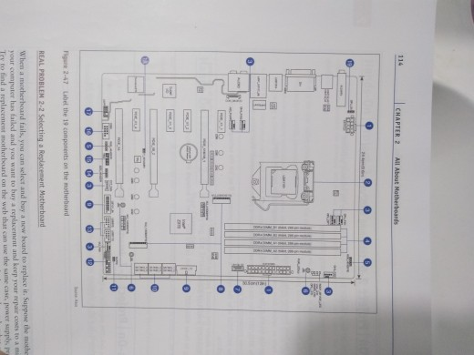
Solved 114 CHAPTER 2 All About Motherboards 0 E O е о Figure ...
eevibes.com › digital-logic-design › how-to-design-aHow to design a four bit adder-subtractor circuit? - EE-Vibes Jun 05, 2022 · Designing: A single basic binary adder may do both addition & subtraction tasks. As illustrated in the diagram underneath, a binary circuit may be created by combining an Ex-OR gate alongside every full adder. 4-bit parallel adder and 4-bit parallel subtractor shown below has multiple 4 bit inputs labelled ‘A3 A2 A1 A0’ & ‘B3 B2 B1 B0’.
BTX - Balanced Technology eXtended - Motherboard Form Factor
Laptop schematic. Laptop motherboard schematic diagrams, laptop ... Laptop schematic. Laptop motherboard schematic diagrams, laptop ...

SOLVED: Want diagram of motherboard - Fixya
Computer Motherboard - Labelled diagram - Wordwall Computer Motherboard - Labelled diagram CPU socket, DIMM, PCIe x16, Northbridge, Southbridge, PCI, SATA, Battery, Analog Audio I/O, USB, 4 pin 12V CPU Power connector, PS2 ports, 24 pin ATX Power connection, PCIe x1. Computer Motherboard Share by Sneekylinuxa1 KS2 KS3 Adult Education Computing Like Edit Content More Leaderboard Log in required
10 Parts of a Motherboard and Their Function - TurboFuture
› SavioAberneithie › twitterTwitter sentimentanalysis report - SlideShare Nov 06, 2018 · Twitter Sentiment Analysis Project Done using R. In these Project we deal with the tweets database that are avaialble to us by the Twitter. We clean the tweets and break them out into tokens and than analysis each word using Bag of Word concept and than rate each word on the basis of the score wheter it is positive, negative and neutral.

label a motherboard pt-2 Diagram | Quizlet
Laptop Motherboard Diagram With Labels Pdf : Dell Inspiron 15 3000 ... Labeled diagram of acer motherboard. Cross reference, circuit and application notes in pdf format. Since schematics diagrams a in pdf format, you need a pdf reader . A quick introduction to installing a free pdf viewer. At the first, look at the bottom of your laptop. This is why this article talks about the different ways by which you can

A technical drawing of a motherboard. Leaders are opo -type ...
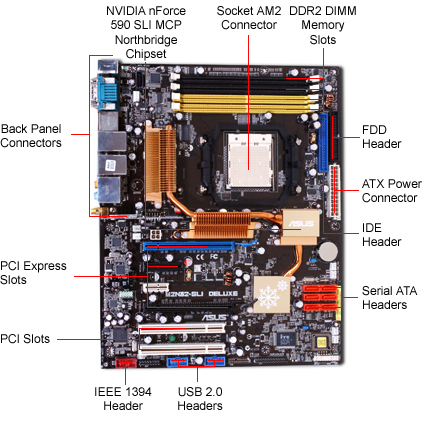
ATX motherboard diagram - Escotal.com ATX MOTHERBOARD DIAGRAM . A. Parallel/Serial Port B. USB Ports C. PS/2 Connector D. ATX Power Socket E. CPU Slot 1 F. Northbridge Chipset G. DIMM Slots H. Primary and Secondary IDE Controller I. Floppy Drive Controller J. CMOS Battery Holder K.Southbridge Chipset L. ISA Slot M. PCI Slot N. AGP Slot O. ROM/BIOS Chipset

A Motherboard Tour - iFixit
› writings › consolesSuper Nintendo Architecture | A Practical Analysis Jun 28, 2019 · Original; Marked; Motherboard Showing revision 'SNS-RGB-CPU-01' Earlier revisions had the Sound Subsystem connected as a daughterboard, later ones unified both PPUs Motherboard with important parts labelled
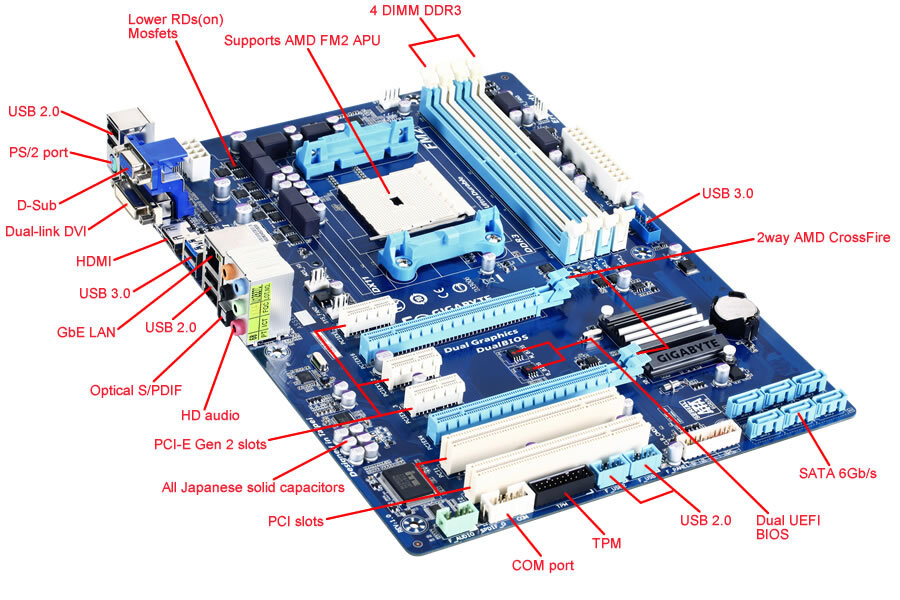
GA-F2A75-D3H (rev. 1.0) Gallery | Motherboard - GIGABYTE Global
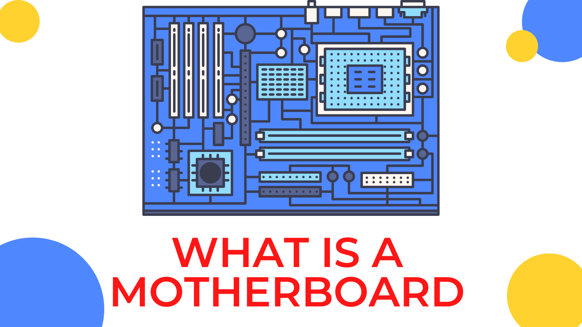
What is a Motherboard? Definition & Diagram PC Motherboard Component and Their Features PS2 Mouse Ps/2 Mouse Connector Circular In Shape 6 Pins Female Type of Connector Usually Green In color PS2 Keyboard Port PS/2 Keyboard Connector Circular In Shape 6 Pins Female Type Of Connector Usually Violet In Color Serial Port Serial / Normal Mouse Connector D-Shape Connector 9 Pins

Motherboard Labeled Diagram Store, 50% OFF | www ...
A Diagram (and Explanation) of Motherboard Parts and ... - Tom's Hardware Below we'll diagram most of the major ports, headers, and slots common on today's motherboards, followed by some helpful basics about expansion slots, RAM, and motherboard form factors. For more...
Foundation Topics: Motherboards and Their Components ...
Sega Saturn Architecture | A Practical Analysis 03/08/2019 · Remaining RAM chips are fitted on the back Motherboard with important parts labelled. Diagram Main architecture diagram. A quick introduction . Welcome to the 3D era! Well… sorta. Sega enjoyed quite a success with the Megadrive so there’s no reason to force developers to write 3D games right now. Just in case developers want the extra dimension, …
Introduction of Motherboard with labelling parts
PDF IDC-Online IDC-Online
Anatomy of a Motherboard | TechSpot
Motherboard Diagram | Block Diagram Template - Visual Paradigm Visual Paradigm Online (VP Online) is an online drawing software that supports Block Diagram and a wide range of diagrams that covers UML, ERD, Organization Chart and more. It features a simple yet powerful editor that allows you to create Block Diagram quickly and easily. Explore more Block Diagram templates 5 Whys - Caught Speeding

A+ motherboard 1 Diagram | Quizlet
Motherboard - Labelled diagram - Wordwall Motherboard name and Model, SATA 1 Connector, CMOS Battery, North Bridge , South Bridge , 24 Pin ATX Main Power Connector, CPU Socket, SATA 2 Connectors, IDE Connector - PATA, 4x4 12V ATX Connector, PCIe Expansion slot, Floppy Disk Controller, RAM slots, Socket Type, Front Panel Connectors, PCI Expansion slot, RAM type and speed. Motherboard Share
Motherboard Labeled Diagram Store, 50% OFF | www ...
Labelled Diagram of a Motherboard | 3D Warehouse View in AR. This is a 3D model to show Computer Science students what goes into a PC. Helpful for most curricula. (It includes other models from the 3d Warehouse.) #Computer_Science #CPU #Motherboard. Electronics Computers.

Motherboard Labeled Diagram Store, 50% OFF | www ...
What is a Motherboard? - Definition, Function & Diagram The base of a motherboard consists of a very firm sheet of non-conductive material, typically some sort of rigid plastic. Thin layers of copper or aluminum foil, referred to as traces, are printed...

computer mother board / Parts of a Mother board and Their ...
How an Inverter Functions, How to Repair Inverters – General Tips 03/08/2020 · Need circuit diagram for this and related parts if required for this stage to remove fault. Please guide me thanks. Reply. Swagatam says. May 22, 2022 at 5:42 pm. This problem is specific to your inverter design, it can be difficult to get the circuit diagram of your inverter and troubleshoot the fault. Reply . Andre Smith says. May 6, 2022 at 3:20 pm. I have a 1200VA …
Jual paket ASUS H61 i3 2120 Indonesia|Shopee Indonesia
Motherboard Labelled Diagram - Edugeek Motherboard Labelled Diagram. Hi All, Thought this might be of interest for anyone that is teaching GCSE ICT or something. Interactive diagram showing components of a motherboard. Intel® Desktop Board DH61CR Interactive Layout.
Motherboard - Teaching resources
eevibes.com › digital-logic-design › draw-the-statehow to draw state diagram of sequential circuit? - EE-Vibes Jun 06, 2022 · The input value that triggers the state shift is the first to be labelled. The value of the output is the number after the slash symbol /. The directed line from state 00 to 01, for example, is labelled 1/0, which means that if the sequential circuit is in a current state with a 1 as an input, the following state is 01 with a 0 as an output.
Basic computer Hardware Concepts.
› writings › consolesSega Saturn Architecture | A Practical Analysis Aug 03, 2019 · Original; Marked; Motherboard Showing 'VA8' revision which includes all components in a single board Remaining RAM chips are fitted on the back Motherboard with important parts labelled
Compal OEM LA-2922P HBL50, Laptop motherboard ...
Motherboard Diagram - Custom Build Computers

File:ASRock K7VT4A Pro Mainboard Labeled English.svg ...
Labelled Diagram of a Motherboard | 3D Warehouse
Apa SSD bisa dipasang di motherboard tipe apa saja? - Quora

What is a Motherboard? - Definition, Function & Diagram Video

VIA KT400 Motherboard Roundup - www.sharkyextreme.com

An example of many-to-one boundary labeling. | Download ...
Computer Motherboard And Its Components,constituent components
What is a Motherboard?
Labeling the MotherboardFigure 3-58 shows a blank diagram ...
A Diagram (and Explanation) of Motherboard Parts and Their ...
What is a Motherboard and its functions? - Digikul.net

Diagram of a typical motherboard | Function diagram, Computer ...

Motherboard | Components | Function | Diagram
Post a Comment for "42 labelled diagram of motherboard"